
EXTERNAL OIL FIRING PROCEDURE BY LOCAL FURNACE
INTRODUCTION AND GENERAL DESCRIPTION
This procedure relates to the application of high velocity oil fired technique for stress relieving of higher Thk walled vessel by external oil fire heat treatment to achieve stress relief temperature of 620°C the mode of heating will be by using high velocity burner.
The heat treatment specifications and temperature constraints as per API 650 10TH Edition and ASME SECTION VIII Div 1.The job should have provision to enable free expansion & contraction of the vessel. The vessel shall be placed on a platform 300mm to 400mm above the foundation or shall be placed on the ground level (uniform flat surface) Uniform flat surface is very essential to ensure smooth expansion /contraction of the vessel during heating/cooling.The job shall be supported with minimum radial or according to size of job .
-
The use of HEXIGON, high velocity burners is an effective method of curing and drying out moisture from refractory materials in the startup process. Working under carefully controlled conditions, we can eliminate the risk of damage that can be caused by spelling and thereby extend the life of the refractory.
-
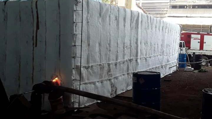
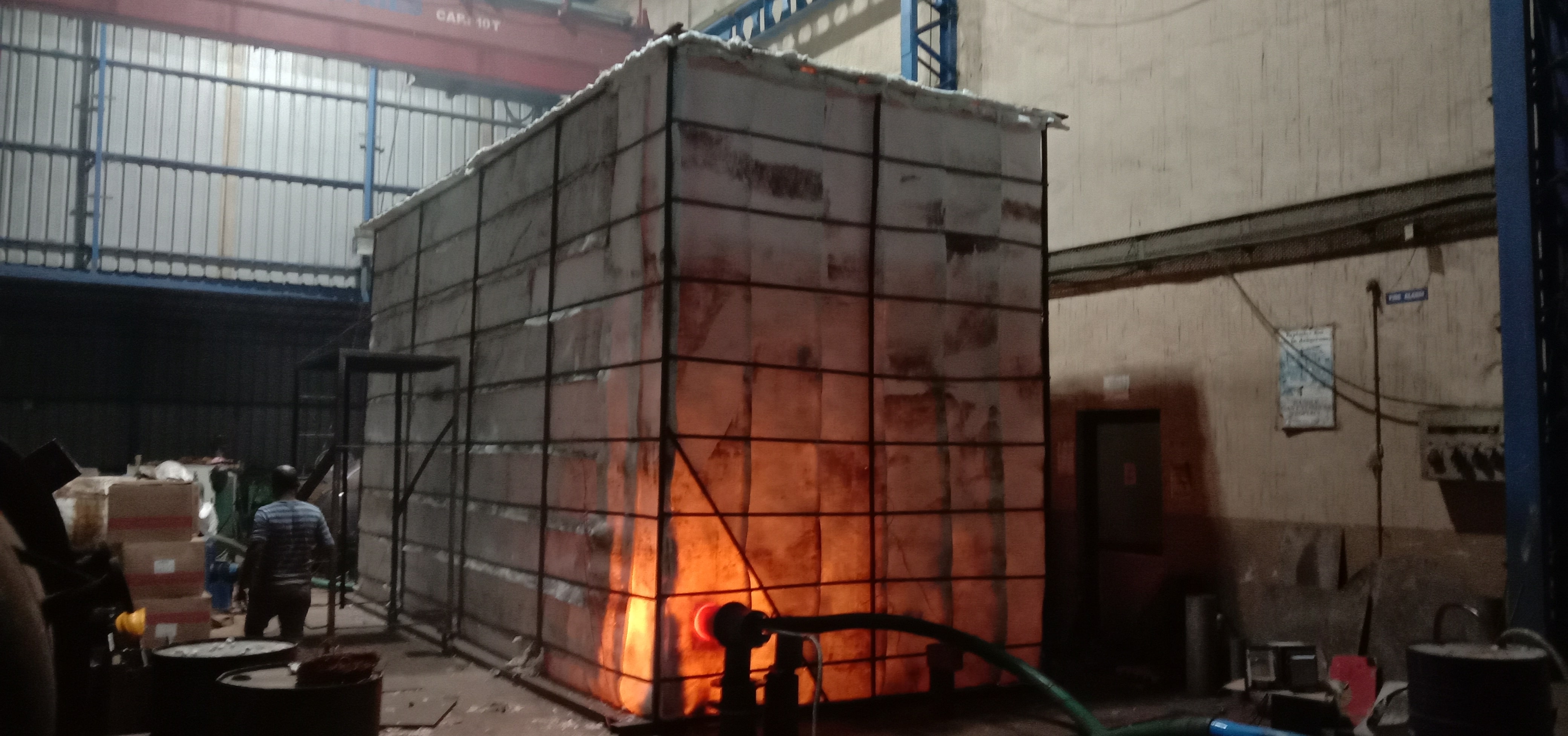
By external firing method large vessel seam LSR operation will be carried out by applying heat under controlled conditions using HAL high velocity fuel fired burners inserted via suitable openings into the temporary furnace and the products of combustion exhausted through suitable openings to the top of the furnace with dampers arrangement.
-
A large variety of Tanks, LPG Bullets, Pressure Vessels, Spheres and welded fabrications structures can be subjected to Post Weld Heat Treatment by utilizing the” HAL High Velocity Burners. Temporary furnace can be built around the items to be treated or insulation can be applied directly to the outer surface and the item turned into its own furnace. The temperature uniformity that can be achieved by this method ensures that even the tightest standards and specifications are comfortably satisfied. The method used to heat treatment would be by means of a high velocity burner inserted into the vessels by means of suitable man way Throughout the heating and cooling cycle the expansion and contraction of the job must be closely monitored and controlled to avoid any distortion of the structure.by means of suitable man way Throughout the heating and cooling cycle the expansion and contraction of the job must be closely monitored and controlled to avoid any distortion of the structure.
-
We propose that a temporary furnace to be fabricated of Scaffolding pipes or MS channel/flats/angles to be erected at site to carry out the stress relieving cycles. The furnace walls and roof will be insulated with one layer of 50 mm thick 96kg/m3 glass wool. The hearth shall be covered with 150 mm thk sand or 50 mm thick 96kg/m3 glass wool . We propose that the job will be loaded in furnace from top of the furnace. The Exchangers should have provision to enable free expansion of contribution of the job. The job shall be placed on a plat form or placed on the ground (Uniform Flat surface) to ensure smooth Expansion/contraction of the exchangers during heating /cooling.
-
The high velocity burner will be inserted from the opening in the sidewalls of the furnace. The burner position is such that circular flow of hot fuel gases is created inside the furnace, which ensures excellent temperature uniformity inside the temporary furnace. The high velocity of the burner produces a scrubbing action on the shell surface, increasing the temperature uniformity. Care is taken to ensure that there is no flame impingement on any part of the vessel or section inside the temporary furnace. The high velocity burner will be controlled manually by continuous monitoring of temperature recorder. Control of temperature will be done by manual adjustment of oil flow/pressure and by butterfly valves of blower (combustion air). The turndown ratio of the high velocity burner is to the tune of 20:1, which gives high degree of control at all stages of firing. As the primary flame of the burner is enclosed in the main combustion chamber, at no time, the flame impinges on the vessel surface, totally avoiding hot spots. Exhaust gases will be taken out from suitable openings provided in the roof of the furnace.
-
Calibrated thermocouple will be installed at suitable locations as per the code requirement connected to the multipoint calibrated ‘K’ type temperature recorder through colour coded compensating cables. Temporary furnace erected of scaffolding material will be externally insulated with one layer of 50 mm thick glass wool, 96 kg/m3 density. The insulation mats will be enmeshed in chicken wire mesh. All the gaps between the insulation mats will be plugged with insulation prior to each charge of temporary furnace. The hearth of furnace shall be prepared of sand at site. Thermocouple will be located over the length as per specifications. Thermocouples will be attached to the grider either with thermocouple nuts or with thermocouple attachment unit.
-
2 nos. High Velocity burner (HSD fired) will be inserted from openings mad on the sidewalls of the temporary furnace. The combustion equipment will comprise of burner, blower, pilot burner with spark ignition system, flexible hoses and control station. Heat cycle profile control will be achieved by controlling fuel flow and combustion airflow through regulating valves.
-
The thermocouple wire (T/C) will be of CR/Al i.e. K type of 1/22 SWG, which will be attached to the shell either by thermocouple attachment unit or by thermocouple nuts. Copper constantan compensating cables will be used for the connection between T/C wire and temperature recorder. The copper lead (+ve) will be connected to the Cr-A1 conductor (non magnetic) and the constantan lead (-ve) lead to the Ni-A1 conductor (magnetic). Each thermocouple will be connected to a calibrated continuously monitoring temperature recorder, thus providing temperature chart print out giving information on temperature variations and trends during the SR cycle. The chart will be presented as a record of the heat treatment cycle. The recorder will be adjusted from a range of 0˚C-1200˚C with appropriate chart speed. Latest calibration certificate of the thermocouple wire & temperature recorder will be submitted before start of the SR cycle. The thermocouple recorder will be calibrated immediately before the first heat treatment cycle and then at intervals not exceeding 6 months or 1 year.
JOB SPECIFICATION
The heat treatment described within this procedure is based on client requirement.
POST WELD HEAT TREATMENT SPECIFICATION
Unrestricted heating rate up to 300°C Heating rate of maximum 100°C/Hr. With a temperature differential of not more than 70°C between thermocouples. Soaking temperature of 620°C +/- 20°C. Soak Duration 2hr and 30min Cooling rate of maximum 70°C/Hr. with a temperature differential of not more than 70°C between thermocouples. Unrestricted cooling rate from 300°C.
Temperature constraints
Based on the above heat treatment specification, the temperature constraints, applicable per API 650 will be followed as under.
| Maximum Differential Temperature | |
|---|---|
| Constraints-1 All thermocouple below 300°C | Unrestricted |
| Constraints-2 All thermocouple above 300°C | +/- 30°C |
| Constraints-3 All thermocouple during soak period | 620°C +/- 20°C |
| Constraints-4 All thermocouple below 620°C | +/- 30°C |
| Constraints-5 All thermocouple below 300°C | Unrestricted |
EQUIPMENT Combustion equipment details for internal oil firing method
- Burner type: 1 no. /02 nos .High velocity Burner.
- Fuel : HSD (diesel)
- Mounting of Burner: will be fired through manhole with appropriate straight or Angle cones per nozzle orientation.
- Blower : 5hp Ignition : with the help of flame Burner management train : comprises of HSD flow control valve, oil pressure regulator ignition transformer.
- Compressed air line FRL & control valve unit & LPG pilot ignition system with line.
Temperature control
- The high velocity burners will be controlled manually by continuous monitoring of temperature recorder.
- Control of temperature will be done by manual adjustment of HSD flow/pressure and by butterfly valves of blower (combustion air )
- The turndown ratio of high velocity burner is to the tune of 20:1 which gives high degree of control at all stages of firing ,as the primary flame of the burner is enclosed in the main combustion chamber & at no time ,the flame impinges on the vessel surface , totally avoiding hotspot.
SITE ELECTRICAL POWER REQUIREMENTSl
The electrical power requirement within 3metres of our equipment at site is 415 volts,3 phase , 4 wire , 50Hz supply of following capacity
- Combustion air blower : (5 Kw x 2) = 10.00Kw
- Pump and other accessories (approx) = 8.00Kw
- Lighting and other (1 Kw) = 1.00 Kw
TEMPERATURE RECORDING
1. The thermocouple wire (T/C) will be CR-AL i.e. K type 1/22 swg , which will attached to the vessel by thermocouple attachment unit.
3. Each thermocouple will be connected to a calibrated continuously monitoring temperature recorder, thus providing temperature chart print out giving information on temperature variations and trends during the SR cycle.
4. The chart will be presented as a record of the heat treatment cycle . The recorder will be adjusted for a range of 0°C - 1200°C with appropriate chart speed.
5. Last calibration certificate of the thermocouple wire and temperature recorder will submitted at the time of meeting as on date (03/02/2019).
6. he thermocouple location on the vessel will be as per Drg.No.
STRESS RELIEVING PROCEDURE
- Before final placement of vessel on saddle supports or on platform , 1 layer of cerawool ,25 mm Thk . Insulation material of density 96 kg/m3 shall be laid on ground/ support, so that the base of the tank rest on the insulated ground /support. Then the entire vessel shell and roof will be externally insulated with one layer 25 mm Thk 25% overlapping insulation material of density 96 kh/m3 . The insulation mats will be plugged before in chicken wire mesh. All the gaps between the insulation mats will be plugged before SR.
- hermocouple will be located circumferentially as per codes requirement & staggered. Thermocouple will be attached to the vessel as described above.
- 02 nos. High velocity burner (HSD fired) will be inserted from manhole openings available on vessel. The approx amount of HSD require for stress relieving shall be 22 liters per ton weight of vessel.
- 02 nos. High velocity burner (HSD fired) will be inserted from manhole openings available on vessel. The approx amount of HSD require for stress relieving shall be 22 liters per ton weight of vessel.
- The combustion equipment will comprise of burner, blowe, flexible hoses, and control station.
- Heat cycle profile control will be achieved by controlling fuel flow and combustion airflow through regulating valves.
RESOURCES AND PERSONNEL PLAN
Site organization & Manpower Planning
- Project manager
- Site Heat treatment supervisor.
- Heat Treatment Technician cum Operator (Site).
- Helper as and when required.
Equipments List
- For above work will mobilize 2 sets of High velocity Burner system.
- 06 point Temperature Recorder as per require.
- Oil pump : 02set
- Wire type Thermocouple
- Reading cable
- Too Box
DOCCUMENTATION AND RECORDS
Site supervisor will be appointed to liase with the client site representative and ensure compliance of procedural requirements. The site supervisor responsible for all documentation.
The documentation will comprise of the following
- Details of thermocouple lay out.
- Heat treatment record sheet as applicable.
- Time temperature chart with details of heat treatment specifications, job specifications, chart speed, date of operation etc.
- Record and thermocouple calibration certificates.
SAFETY
- All burner and associated equipment will be checked and test fire prior to dispatch to site.
- The site engineer will be designated as the safety officer on site to ensure that all site operation is carried out in accordance with accepted safe working practices. He will be responsible to ensure that all site safety requirements are fully met and complied .