
PWHT PROCESS BY RESISTANCE HEATING IN WELD JOINTS Method
HEXIGON offers a full range of heat treatment services through a wide range of temperatures. We utilize both electrical and fuel fired methods as a source of heating with the objective of bringing your project in on time and on budget
Thermal stresses occur as molten weld pools cool at which point cracking can occur both during and after welding. Moreover, the colder parent or base metal resists the inevitable contraction of the weld metal. In some instances heavy wall materials and aluminum alloys with higher thermal conductivity can act as a heat sink, drawing heat away from a weld and cooling at an accelerated rate.
If moisture is present at a welded joint, the high heat of the welding arc will break the water down into its elements, hydrogen and oxygen. The hydrogen by-product easily dissolves into the weld metal and causes weld porosity during weld solidification. During and after completing of the welding process, both the weld pool and the heat affected zone (HAZ) can harden and crack when cooling at a rapid pace.
Pre heat treatment is used to prepare the base metal work area so as to improve the integrity of the weld or machining process by raising the temperature gradually thereby improving ductility in advance of the work taking place. This enables the higher temperature area to respond more effectively to the weld or machining process.
General Instruction
-min.jpeg)
-
All the relevant instruments such as thermocouples, recorder and controller should have valid Calibration certificate traceable to National Standards.
- The Thermocouples to Extension Cable Connection shall be clear of the. heating Zone
- The item should be free from grease, oil, did & spatter beforePtI/HT is carried out.
- During the heating period there shall not be a greater variation in temperature throughout the portion of the item being heated than 250°F (140°C) within any .15ft: (4.6m) interval of length.
- • During the holding period, there shall not be a greater difference than 150°F (83°C) between the highest and lowest temperature throughout portion of the item being heated
- minimum Local PWHT soak band width measured from the toe of the greatest width of the weld shall be twice the shell thickness measured on each side of the weld.
HEATING ELEMENT & INSULATION
-
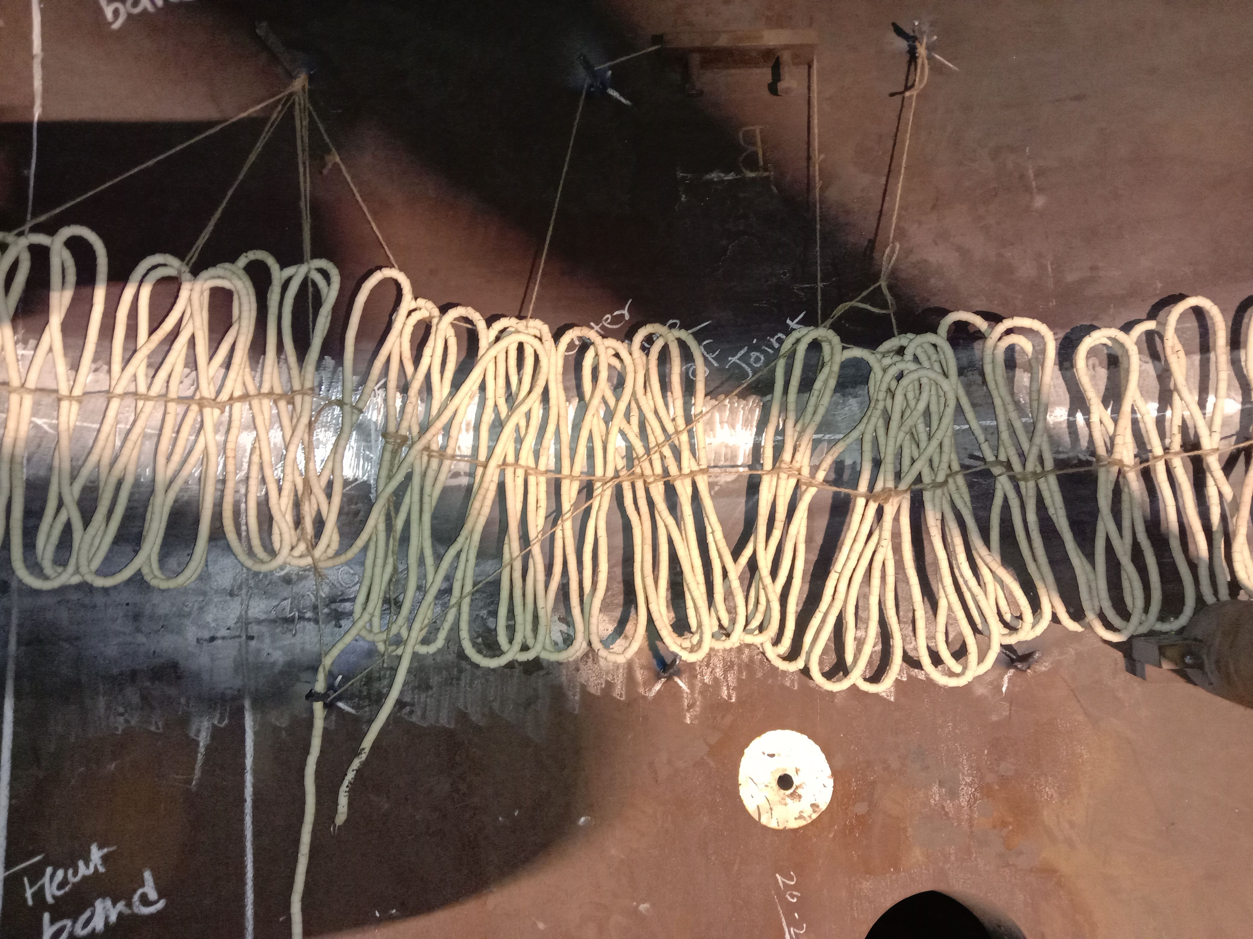
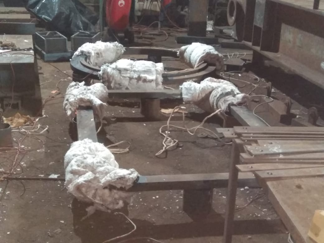
Special type of finger elements rated 8kW at 230V each shall be wrapped circumferentially in three-control zone from both sides. About 50mm thick (in free condition) ceramic fiber insulation shall be wrapped circumferentially around the soaking band, heating band & insulation band. The insulation shall be held tightly with the help of binding wire or studs.
- Soak Band: The volume of metal that shall be heated to the heat treatment temperature range. As a minimum the
LOCATION OF THE SUPPORT
- Equipment shall be loaded on appropriate support
- Support of minimum 250mm width and job should be minimum 200mm above floor level.
- Require support as per job.
Heat Band
The heat band (HB) is the surface area over which the heat source is applied to achieve the required temperature in the SB. The lowest temperatures recorded on the outer edge of the HB on the inside as well as on the outside of heat treated component shall be not less than half of maximum temperature in the SB at the time. The minimum Local PWHT heated-band width shall be distance 2g (RT measured from the edges of soak band each side, where R is the internal radius and T is thickness of the shell..
Gradient Control Band / Insulation Band
The insulation band (IB) is the area over which the insulation is placed. It encompasses the SB, HB and sufficient base metal to avoid excessive axial temperature gradients. The minimum L-PWHT insulation band width shall be 44 (RT) measured from the edges of soak band each side. Where R is cylinder internal radius, T is shell thickness.
LOCATION OF THERMOCOUPLE
Contact Type K (Chromel- Alumel) or Type J (iron- Constar tan) thermocouples will be placed on the job to record the temperature.
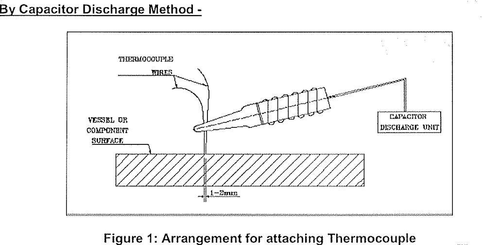
Method of attaching Thermocouple
- Identify the area where the thermocouple to be attached
- Clean the area with emery paper
- Charge the capacitor
- Both the thermocouple shall be directly welded on the surface of weld joint and maintain 1 to 2 mm of distance between two wires of thermocouple.
- Catch the thermocouple place it to proper location and weld with capacitor discharge welding as per the WPS- CDW01 REV 0
Method of removal of Thermocouple
- After Complation of PWHT, all Thermocouples shall be removed and attached areas ground smooth to clean and sound metal. DPT/MPT to be carriedout after grinding.
INSPECTION
The arrangement for heat treatment loading and unloading will be witnessed by NECL
following documents will be produced at the end of heat treatment.
- Job detail.
- Actual loading temperature.
- Actual heating rate vs specified heating rate.
- Actual soaking temperature vs specified soaking temperature.
- Actual soaking time vs specified soaking time.
- Calibration certificates of temperature recorder and thermocouple.