
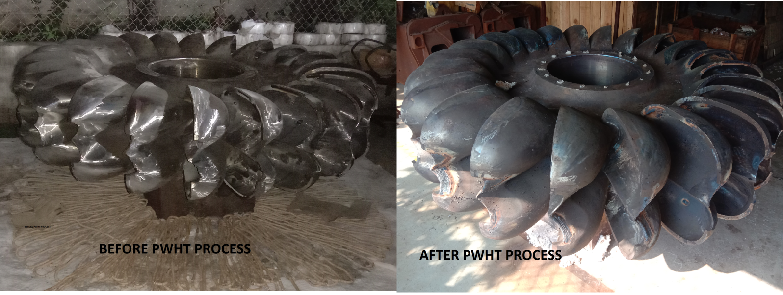
PWHT PROCESS BY RESISTANCE HEATING IN LOCAL FURNACE

HEXIGON offers a full range of heat treatment services through a wide range of temperatures. We utilize both electrical and fuel fired methods as a source of heating with the objective of bringing your project in on time and on budget.
Thermal stresses occur as molten weld pools cool at which point cracking can occur both during and after welding. Moreover, the colder parent or base metal resists the inevitable contraction of the weld metal. In some instances heavy wall materials and aluminum alloys with higher thermal conductivity can act as a heat sink, drawing heat away from a weld and cooling at an accelerated rate. If moisture is present at a welded joint, the high heat of the welding arc will break the water down into its elements, hydrogen and oxygen. The hydrogen by-product easily dissolves into the weld metal and causes weld porosity during weld solidification. During and after completing of the welding process, both the weld pool and the heat affected zone (HAZ) can harden and crack when cooling at a rapid pace.
Pre heat treatment is used to prepare the base metal work area so as to improve the integrity of the weld or machining process by raising the temperature gradually thereby improving ductility in advance of the work taking place. This enables the higher temperature area to respond more effectively to the weld or machining process.
Pre heat treatment is used to prepare the base metal work area so as to improve the integrity of the weld or machining process by raising the temperature gradually thereby improving ductility in advance of the work taking place. This enables the higher temperature area to respond more effectively to the weld or machining process.
General Instruction
-
All the relevant instruments such as thermocouple, temperature recorder and controllers shoud have valid calibration certificate traceable to National Standards.
- The thermocouple to extension cable connection shall be clear of the heating Zone.
- The item should be free from grease ,oil, dirt & spatters before PWHT is carried out.
- The copper lead (+ve) will be connected to the Cr-A1 conductor (non magnetic) and the constantan lead (-ve) lead to the Ni-A1 conductor (magnetic)
- Each thermocouple will be connected to a calibrated continuously monitoring temperature recorder, thus providing temperature chart print out giving information on temperature variations and trends during the SR cycle.
- The chart will be presented as a record of the heat treatment cycle.
- The recorder will be adjusted from a range of 0°C -1200°C with appropriate chart speed.
- Calibration certificate of thermocouple and temperature recorder will be submitted before start of the SR cycle.
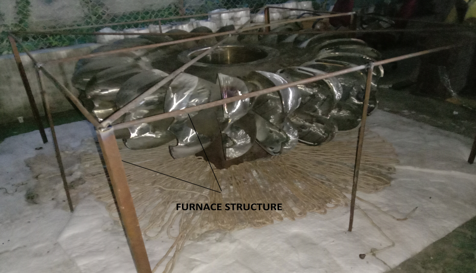
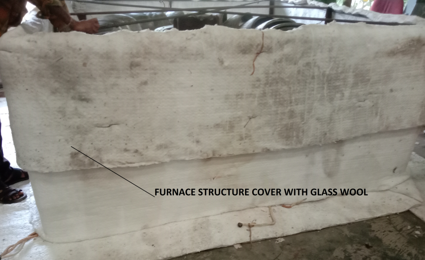
- Temporary furnace erected of scrap material will be externally insulated with one layer of 30mm thick glass wool insulation, 96 kg/m3 density as per photos.
- The insulation mats will be enmeshed in chicken wire mesh.
- All the gaps between the insulation mats will be plugged with insulation prior to each charge of temporary furnace shall be prepare of glass wool.
- Thermocouple will be located over the length as per specifications.
- Thermocouple will be attached to the grider either with thermocouple nuts or with thermocouple attachment unit.
- Equally distributed 12, SWG Nicrone wire coils by fingering method over insulated ground.
- The thermocouple wire (T/C)will be of CR/AL, “K” TYPE ,1/22 SWG, which will be attached to the runner either by thermocouple
- The coils position in such that circular flow of hot air is created inside the furnace, which ensures excellent temperature uniformity inside the local temporary furnace.
- The high voltage coils produces a scrubbing action on the runner surface, increasing the temperature uniformly.
- Care is taken to ensure that there is no hot coils impingement on any part of the runner or section inside the local furnace.
- The high voltage coils will be controlled manually by heating panel.
- Control of temperature will be done by manual adjustment of sun beam.
- Calibrated thermocouple will be installed at suitable location as per the code require.
- Runner must be closely monitored and controlled to avoid any distortion of the structure, means of suitable man way through the heating and cooling cycle the expansion and contraction of the runner must be closely monitored and controlled to avoid any distortion of the structure.
- We proposed that first of all put the runner over balancing support then pack it with local furnace. the runner should have provision to enable free expansion of contribution of the runner.
- The runner shall be placed on a platform or placed on the ground (uniform flat surface)to ensure smooth expansion/contraction of the runner during heating/cooling.
Post weld heat treatment
-
elding deposits, which is in molten state at high temperature and expanded form, is applied to the cooler base metal with which it is bonded. Weld material is rapidly cooled and it attempts to shrink. However, the bonded weld and the base material resists the shrinkage phenomenon and residual tensile stresses is induced .the stress level in the weld zone after cooling can be as higher as yield strength of the base material and these stress may exceed the design stress when combined with the normal stress during operation which causes failure. Metal shows volatile nature at higher temperature and residual stress caused by welding are able to relive themselves.
- A higher temperature and longer holding time helps in relieving higher residual stress. Therefore, it is necessary to relieve the residual stresses due to welding by PWHT in addition, hydrogen present in the weld zone are diffused at higher temperature during PWHT which reduces the risk of corrosion cracking and hydrogen induced cracking.
- The temperature of the runner was longed during PWHT at six different locations. The average temperature plot of heat treatment of the runner and prescribed heat treatment conditions is show in chart in general heating rate is not much important. The rapid cooling helps to avoid the formation of chromium carbide that induces corrosion and root cracks which accurse due to corrosion fatigue. The cooling rate should be slower after reaching the marten site formation temperature .the temperature difference at different section in the runner should not exceed 42°C during PWHT .
LOCATION OF THE SUPPORT
- Equipment shall be loaded on appropriate support
- Support of minimum 250mm width and job should be minimum 500mm above floor level.
- Require 1 Sq support.
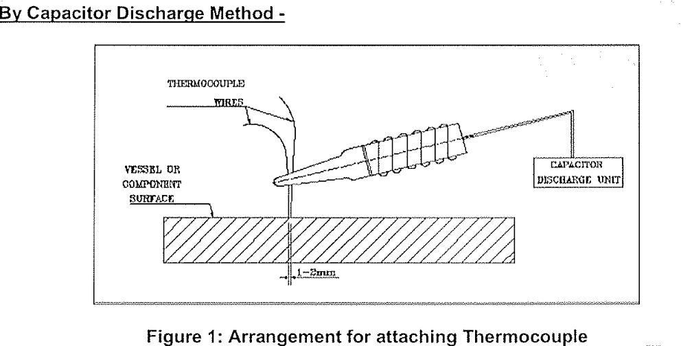
Method of attaching Thermocouple
- Identify the area where the thermocouple to be attached.
- Clean the area with emery paper.
- Charge the capacitor.
- Both the thermocouple shall be directly welded on the surface of weld joint and maintain 1 to 2 mm of distance between two wires of thermocouple.
- Catch the thermocouple place it to proper location and weld with capacitor discharge welding as per the WPS- CDW01 REV 0.
Method of removal of Thermocouple
- After Complation of PWHT, all Thermocouples shall be removed and attached areas ground smooth to clean and sound metal. DPT/MPT to be carriedout after grinding.
INSPECTION
The arrangement for heat treatment loading and unloading will be witnessed by AES Hydro
following documents will be produced at the end of heat treatment.
- Job detail.
- Actual loading temperature.
- Actual heating rate vs specified heating rate.
- Actual soaking temperature vs specified soaking temperature.
- Actual soaking time vs specified soaking time.
- Calibration certificates of temperature recorder and thermocouple.